

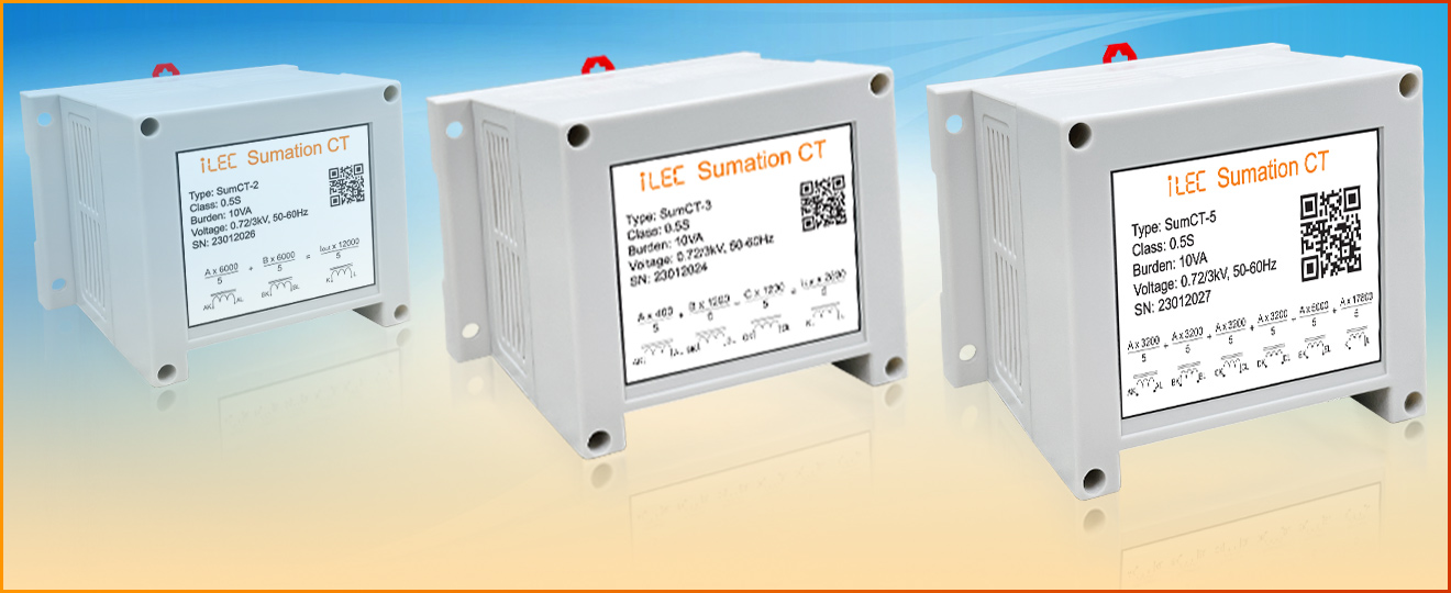
Summation Current Transformer
Model SUMCT
Working Principal
Summation current transformers are used to add up secondary currents of multiple main current transformers to measure with one instrument only.
The currents are always vectorially added under consideration of the amount and phase disposal of the current so it can be used for measuring active or reactive power, energies, and total power factor of the system.
The output signal is again a standardized signal which is received by adding the input currents by the quantity of inputs and the ratio of inputs.
As mentioned above, the currents are always vectorially added, so the output is very different, and not easy to check by any clamp and multimeter. For ease of understanding, we assume the input currents have the same phase angle, only different amplitudes.
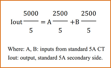
We are considering a summation current transformer with two inputs 2500/5A and one output 52000/5A.
The formula is shown as below:


The sample values for inputs and output as below tables:
| Table 1 : Output current for the same input signals | ||||
| Inputs | A | B | I out | Output current with CT Ration 2000/5 (A) |
| 5% | 0.25 A | 0.25 A | 0.25 A | 100 A |
| 20% | 1.0 A | 1.0 A | 1.0 A | 400 A |
| 50% | 2.5 A | 2.5 A | 2.5 A | 1000 A |
| 100% | 5.0 A | 5.0 A | 5.0 A | 2000 A |
| 120% | 6.0 A | 6.0 A | 6.0 A | 2400 A |
| Table 2 : Output current for one input signal A | |||||
| Input A | A | Input B | B | I out | Output current with CT Ration 2000/5 (A) |
| 5 % | 0.25 A | 0 % | 0.0 A | 0.125 A | 50 A |
| 20% | 1.0 A | 0 % | 0.0 A | 0.5 A | 200 A |
| 50% | 2.5 A | 0 % | 0.0 A | 1.25 A | 500 A |
| 100% | 5.0 A | 0 % | 0.0 A | 2.5 A | 1000 A |
| 120% | 6.0 A | 0 % | 0.0 A | 3.0 A | 1200 A |
- The ratios of the main unequal CTs have always been advised together with the order because the primary input currents are always weighted accordingly. The ratio of the primary currents should not be more than 10 : 1 (biggest to smallest primary current).
- The sum of the currents can add up to Zero e.g. in case of a differential current measurement. The standard application is the addition of currents of the same phase. With a reverse connection of the main current transformers, it is also possible to subtract currents.
Test diagram:
The easiest way to test the sum CT is connecting all primary inputs in series with the forward direction and test as a 5A:5A current transformer.
Important notes when using:
- Unconnected secondary currents MUST BE short-circuited.
- Unused primary terminals have to remain open and shall never be short-circuited in contrary to the secondary terminals. (avoid keeping unused primary inputs).
- Connecting correct current transformer with exactly ratio to all primary inputs.
- The burden of the current transformer connected to the primary input must be sufficient to ensure the output power.
Applications
- Measuring from two or more distribution transformers for zero-export solar system (LV side).
- Measuring from two or more distribution MCCB / Transformer for one customer.
- Measuring from two or more distribution branches for one capacitor panel.
Specifications
| Parameter | Value |
| Highest voltage equipmen | 720 V |
| Rated insolation level | 3 kV, 1 min |
| Rated shot-time thermal current (Ith) | 50 x In |
| Rated dynamic current (Idyn) | 2.5 x Ith |
| Frequency range | 50/60 Hz |
| Internal consumption | Max. 4 VA |
| Output current | 5 A (1 A can be ordered) |
| Maximum continuous current | 6 A |
| Instrument security factor (FS) | < 5 |
| Thermal class of insulation | E |
| Accuracy class index and burden | Class 0.5 10A, CL0.5S (CL.1 for some unequal CTs) |
| Fixing | DIN-rail or screw fastening |
Ordering Code Structurer
SumCT–x–y
- x : number of input, for unequal CTs, please send ratio for each CT.
- y : number of outputs, (y=1 by default)
Dimension

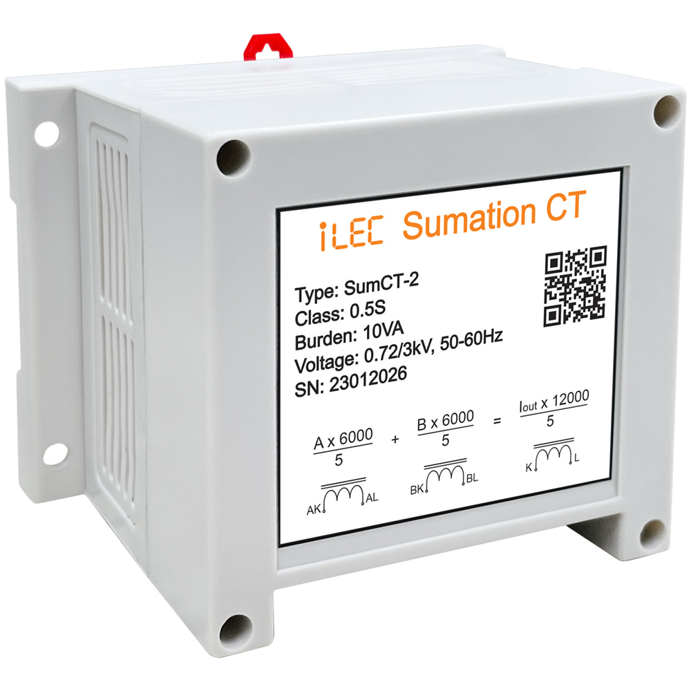
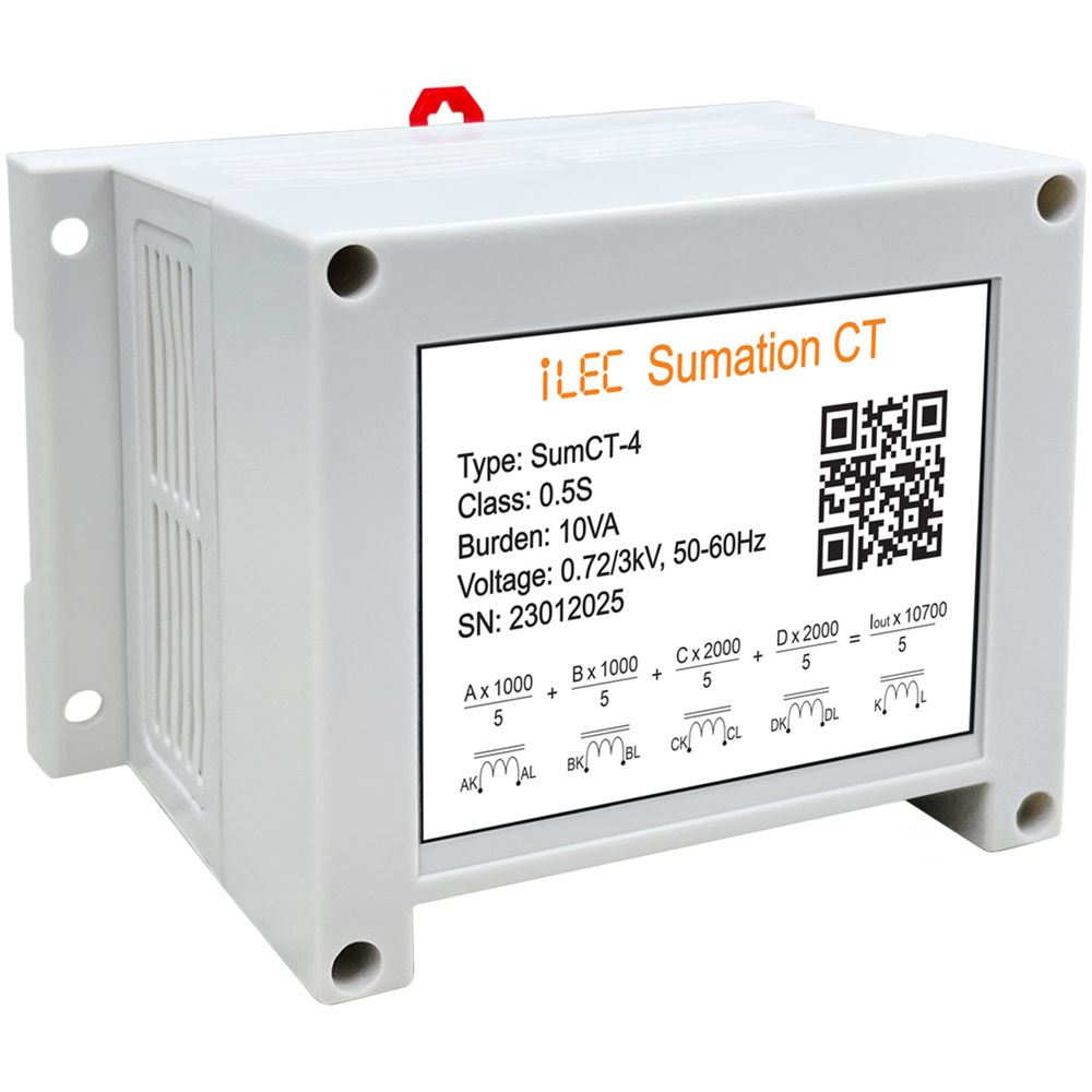
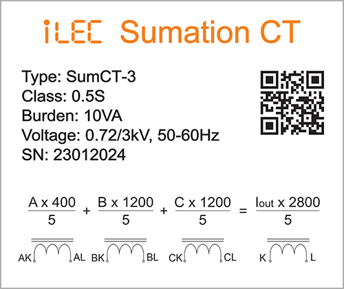
iLEC SumCT nameplate details



Resources & Support
- Technical document: iLEC SUMCT